
Carburetor Tuning for Kawasaki Triples
This manual can be downloaded in PDF format (4.8M) here.
Proper carburetor tuning is essential to having a good, clean running Triple. Improper tuning can lead to engine damage. It is important to not only know what to do but why you need to do it. For that reason, it is strongly suggested that you read the entirety of this manual.
Mikuni VM carburetors are built with four distinct circuits for delivery of fuel/air mixture to the combustion chamber in proper ratios to provide smooth engine operation from start-up through wide-open-throttle position. All of these circuits are metered by throttle position. It is for this reason that throttle position is referenced throughout this manual rather than RPM. A lean condition at an throttle position can result in detonation or pinging which can cause severe engine damage.
Enrichment
The enrichment circuit, commonly referred to as "choke", provides extra fuel to the cylinders to aid in cold starting. Brass, spring loaded, plungers are connected via cables to a lever at the left hand twistgrip. The enrichment circuit will only work properly with a closed throttle.
Low Speed/Idle
The low speed circuit, pilot circuit, provides fuel/air mixture, at diminishing effectiveness, from zero to 3/8 throttle. The component in this circuit are the pilot jet, airscrew, and slide. The idle screws are used to set idle RPM.
Mid-Range
The mid-range circuit primarily affects mixtures at 1/4 to 3/4 throttle positions. It includes the needle jet, jet needle, and, to a lesser degree, the slide.
Hi-Speed
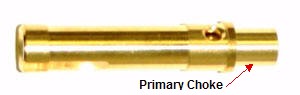
The hi-speed circuit mixture is effective at 3/4 to WOT. The mixture is, almost all, controlled by the main jet size. The primary choke height atop the needle jet is also a factor.
| Throttle Pos | Larger# = | Note: | |
| Air Screw |
0-1/4 | CW rotation = richer Adjust for highest idle RPM. | |
| Pilot Jet |
0-1/4 | Richer | If the best idle mixture screw setting is less than 1 turn out, the pilot jet is probably too lean. If the best idle adjusting screw setting is more than 2 turns out, the pilot jet is probably too rich. |
| Slide Cutaway | 0-3/8 | Leaner | Height of the cutaway notch. Each unit equals .0625", i.e., 2.0 = .125" cutaway. |
| Needle Jet |
1/8-5/8 | Richer | Use the largest number (richest) that will work successfully. |
| Needle |
1/4-3/4 | Richer | The numbers are stamped at the top of the needle. Reducing diameter richens mixture. Taper controls transition rate. |
| Clip Position | 1/8-3/4 | Richer | Clip position is counted from top down. If the motor runs best with the clip in the top notch, the needle taper is too sharp or the needle jet is too large. If the motor runs best with the clip in the bottom notch, the needle taper is too shallow or the needle jet is too small. |
| Primary Choke | 3/4-4/4 | Richer | Height is measured in mm. |
| Main Jet |
3/4-4/4 | Richer | Plug chop after full throttle operation is required to determine the best size for main jet. Too small a main can damage the motor. The motor should run up to 3/4 throttle with the main jet removed. |


Note: Some components are offered for
other type Mikuni carburetors that look similar and will fit but they will NOT
function properly.
Example below:

The pilot jet on the left is NOT correct for any Triple. Be sure the jets used
are exact type and style as shown below and have the Mikuni logo:
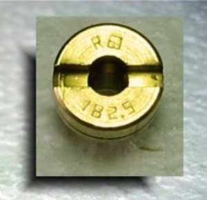
Pilot Jet - VM22/210 Series


Main Jet - Large Round - N100-604


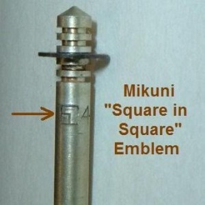
Float Valve - VM26/26 - 2.5


Needle Jet - Various Series
(Note: Kaw OEM or Mikuni needle jets are not commonly available from aftermarket sources)
Needles - Various
(Note: Kaw OEM needles are not commonly available from aftermarket sources)
Needle Information
Air Screw - VM20/214

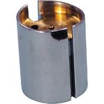
Slide (Throttle Valve) - Various
(Note: Although replacement slides are available, guide slots may not be
accurate for
OEM carb bodies and they may need to be adapted for guide rods.)
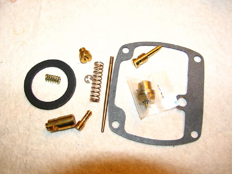
Typical Carb Kit Components
Be aware that jets and needles in most carb kits are not to Mikuni specs and
can cause tuning problems. (photo
example)
Note: This is a generic VM carb that may not be identical to Kawasaki OEM

Videos of disassembly are provided by John Aylor in the links below:
Disassembly video Part 1
Disassembly video Part 2
I - Disassembly
A - Remove float bowl
By slowly & carefully removing float bowl you may be able to save
the gasket for reuse. Use a knife to peel the gasket as the bowl is being
removed. Carefully examine the overflow tube for fracture or loose fit as this
can be a source for leaks.
B - Remove the float
The float is fragile. Bulbs can easily be dented. If they have
recently been submerged in fuel, shake them and listen for fuel inside. They
are prone to leak with minute pinholes from corrosion/oxidation. Pinholes can
be repaired with solder if done properly.
C - Remove float valve
Old float valve assemblies should normally be replaced as they are
prone to leak with corrosion/wear.
D - Remove pilot jet
Always use a screwdriver that has a good square tip as a rounded tip
will easily deform the pilot slot and make removal a serious problem. Note the
pilot size stamped.
E - Remove the main jet
Note the size stamped. Do not lose the
metal washer.
F - Remove the needle jet
The needle jet can be removed by reinserting the main jet for a
couple threads and then tap lightly. This will unseat the needle jet and allow
easy removal. Do NOT pull on the jet at the primary choke shield as it is easily
distorted.

II - Cleaning
A - It is best to soak all parts overnight in a good carb cleaner.
Berryman's or Gunk is available at Autozone, etc. and comes with a dip basket inside a
gallon container. It will not harm phenolic inserts in the carb body. Observe
safety precautions and use in well ventilated area. It stinks!
- If carb cap is being cleaned, remove the gasket to prevent damage.
- If the float is weighted so it will be submerged it can later be
checked for leaks by shaking.
- After soak, blow out ALL orifices with compressed air.
B - An alternative to soaking is to use brake cleaner to clean/blow out all
orifices.
Note: There are several techniques used to restore the original finish to carb
bodies. These should not be confused with cleaning agents designed to
dissolve varnish/gum of fuel residue.
III - Inspection
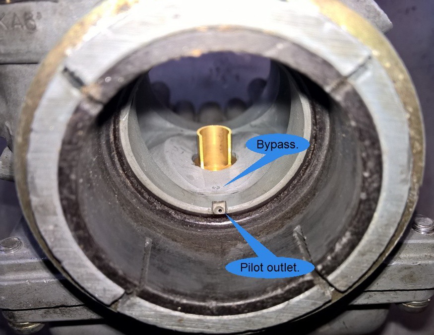
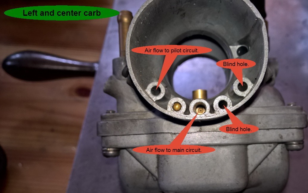
A - All orifices in carb body (including those at air intake) should be
clear. Checking passage
ways video
B - Pilot jet should have clear holes at each end and through the body. A
fine wire (guitar string) can be used to clear holes. It is very important to
not distort or enlarge holes during cleaning.
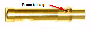
C - The needle jet has an orifice at the side that is prone to clogging.
D - Insure that no fluid is present inside floats.
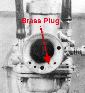
E - Insure that a brass plug resides in one of the ports at
the intake bell of the carb body.
F - Inspect overflow tube in float bowl for hairline splits
and tight fit.
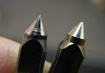
G - Replace float valve
Worn float needle vs. new kit needle

IV - Reassembly
A - Reassemble in reverse order of disassembly.
B - Be sure metal washer is under main jet and fiber washer
is under float valve.
C - Do not over tighten pilot jet.
D - Insure that slides move freely within carb body.
E - Insure that gasket is present and properly seated in cap.
F - Insure that float needle moves freely.
G - Reset float height. Simple gauge:
http://kawtriple.com/mraxl/tips/floatgage.htm
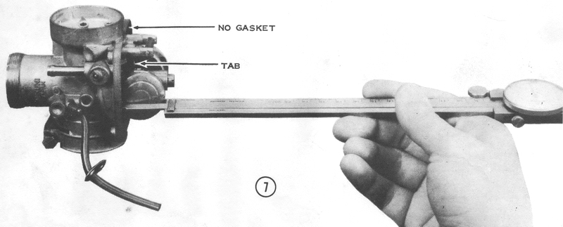
Set float level per spec: http://kawtriple.com/mraxl/carbspec.html This is usually done by inverting the carb and measuring the "float height" in the "at rest" position in reference to the gasket surface with gasket removed. Precise setting is made when the float tang just touches the needle plunger. http://kawtriple.com/mraxl/tips/floatgage.htm "Fuel Level" can be used when using a special float bowl... don't confuse the two terms. If any carb is leaking from the overflow after assembly, this problem must be addressed before continuing with adjustments.
Mount carbs and assure there are no air leaks from missing cap gaskets, loose fit, etc. Set all needle clips to the same position. ref:http://kawtriple.com/mraxl/carbspec.html Be aware that some carbs (S series) will allow slides to be fitted backwards and the clamp space may need to be cut wider to allow tight clamping.
Some models have a phenolic heat insulator sandwiched between two gaskets at the base of the intake manifold to prevent excessive heat transfer from the cylinders to the carbuetors.
Gaskets should be present on all carb caps. A drop of super-glue will insure they stay in proper position.
It is important to understand, no matter what method is used, that carb sync is the act of attempting to get the slides positioned so that they all pass the same airflow at ANY given throttle position. That cannot be done if any slide is resting on an idle stop screw or bottomed out. Idle screw adjustment will NOT sync carbs. Sync can only be achieved though cable adjustment.
Once cables are adjusted for proper sync, the settings should not change except for cable stretch over a longer period.
Be sure to check oil pump adjustment after carb sync is completed.
1) First back off the idle screws untill they don't touch the slides.
2) Carefully screw each one in until the screw just barely touches the slide.
3) Turn in each screw the exact same amount, until you get your target idle number. If you don't do this first, the little variance you get when setting the idle screws will affect slide height and the sync will not be "spot on".
4) Make sure you have slack in the cables.
5) Put your middle finger of your left hand on the center slide, and your thumb (left hand) on the right slide. Turn the throttle very slowly and feel if the slides lift at the same time. If not, adjust one or the other cable so they do.
6) Snap the throttle a couple of times to make sure the slides are setting in well, and tighten the cable lock nut and recheck.
7) Move your thumb to the center slide and your middle finger to the left carb. Adjust the LEFT carb till it lifts exactly with the center.
8) Snap the throttle again and make sure the lock nut is tight (tightening the lock nut will change the slide height).
9) Open throttle until slide is even with top of carb throat. Feel that all slides are at the same position.
10) Take out any extra slack in the cable, AND check the oil pump for correct setting.
The finger method can tell movement in thousands of an inch (just say very accurate). Set the sync from idle, because that is where it is most important.
1) Find a smooth round pin about 3/8" or 10mm dia. (I use the shank of drill bit)
2) Remove air box/filters.
3) Back out slide stop (idle adj) screws.
4) Set throttle lock or set throttle adjuster at the grip so the pin will just lightly drag as it is inserted in the carb throat under the slide cutaway of one carb.
5) Set the other carbs so they offer the same resistance when the pin is inserted by setting the cable adjuster at top of each carb.
6) Release throttle lock or reset throttle adjuster at grip insuring that slides on all carbs will fully bottom out and throttle grip has 2-3mm play.
7) Set air & idle adj screws per topics following for best idle.
As a final check to insure all idle adj screws are set the same, insert a nail, spoon, or long toothpick under each slide without altering slide position. As the grip is turned the ends of all three should tip at the same time. Readjust idle screws as required.
A manometer or Uni-Syn can also be used and may obtain better results IF used properly.
When using a meter for carb sync the sequence of procedures must be altered to achieve desired results.
- Air screw adjustment for highest reading with meter must be done first.
- Slide sync adjustment may then be done with slides positioned off idle screws.
- Idle screw adjustment may then be done.
- Timing can affect performance. Know where your timing is set before making carb adjustments. A couple of degrees can make a big difference in acceleration characteristics. Properly setting timing may cure ills without getting into carbs.
- Gearing can also be a significant factor. Too tall gearing can cause bogging on takeoff when tuning is spot on.
- Exhaust pipes/baffles MUST be clean. Clogged pipes can kill top end.
- Excess carbon on pistons can cloud tuning issues.
- Air leaks and/or bad crank seals can affect tuning. A leakdown test is
strongly recommended.
http://kawtriple.com/mraxl/cranksealtest/cranksealtest.htm
- Float Height must be properly set.
- Enrichment (choke) cables must be set with approx 1/8" free play at carb.
- Low compression can't be compensated for with tuning. Compression specs vary between models but anything less than 140 psi requires attention.
- Change in fuel grades or blends can make tuning requirements change. It is best to use premium fuel.
- If premix is used, it can alter tuning characteristics, as can ratio changes.
- Before making any adjustments be sure the carbs and jets are clean. That means ALL jets... pilot, needle jet, and main, are removed and inspected/cleaned. Carb body passageways should be blown out with brake cleaner or soaked in carb cleaner for several hours and blown out with compressed air. There is a very small air passage in the bell of the carb that clogs very easily and is a major cause of jetting problems. Disassembly video Part 1 Disassembly video Part 2
- Sparkplugs should be NGK B9HS (or B8HS) or equivalent, properly gapped. Extended reach plugs are an absolute no, no, and resistor plugs are discouraged as being problematic, as are resistor caps and wires.
- Unless ALL these prerequisites are met, tuning can prove to be fruitless and frustrating.
- Mikuni VM carbs are designed with three main circuits..... idle, mid-range, full open. Tuning and diagnostics of these circuits is based on throttle position, not RPM. It is a good idea to mark the throttle with tape at various positions when diagnosing problem areas to make it easier to know which circuit requires attention.
- Adjustments should be made with air filters intact as you intent to run. Changes to pipes or air intake may require rejetting. Be aware that pod filters with metal backing can reduce performance and made tuning more difficult.


(Note: VM24 used on S1 & KH250 models are as shown in H1-VM28)
Check the choke cable slack by tugging on the cable sheath at the choke lever. There must be 1/16" to 1/8" slack in the cable with the lever released. If there is no slack in the cable, the enrichment plunger may be held off its seat, causing rich fuel mixtures and increased exhaust emissions, especially at low throttle openings. If the cable slack is excessive, the cold-start system will not work properly, causing difficult starting with a cold engine.
To adjust the choke cables, loosen the adjuster locknut at the handlebar
lever, and then shorten the adjuster till the cable sheath has at least 1/4"
free play. Pull up the rubber boots from the carburetors and loosen the adjuster
locknuts. Turn out the cable adjuster if cable slack is excessive; turn it in if
there is no slack. Tighten the locknuts and replace the rubber boots. Now
lengthen the adjuster at the handlebar lever until the cable sheath has 1/16" to
1/8" free play. Tighten the locknut.
Because of the overlapping of carb circuits it is highly recommended to perform tuning in the sequence shown here... LoSpeed, MidRange, then HiSpeed.
Low Speed
Adjust air screws (one carb at a time) for highest idle RPM with a warm engine. It will require that idle screw is turned to increase RPM for the cylinder to be adjusted. Air screw adjustment should be made at >2000 rpm. Adjustment should be made in slow, small increments. If air screw is out more than 1 3/4 turns for highest RPM, a smaller pilot jet should be fitted. If air screw is out less than 1 1/4 turns, a larger pilot jet should be fitted. Return idle to normal and repeat for next cylinder. Idle RPM should be 1250-1400 RPM.
The airscrew is a fine-tuning adjustment designed to allow the carburetor to be slightly adjusted for variances in atmospheric conditions. The air screw works with the pilot jet, mainly affecting the engines initial starting, idling and initial power delivery. Proper adjustment of the airscrew can offer direct feed back on pilot jet sizing. When adjusting the air screw, tightening the screw is richer and loosening it is leaner.
If you get no RPM fluctuation when adjusting the air screw there is a good chance that there is something clogging the pilot system or the wrong size pilot jet is installed. In most cases, the pilot jet should be the same as original stock, ref: http://kawtriple.com/mraxl/carbspec.html Clean the system thoroughly with carb cleaner and blow out with compressed air.
A lean setting will cause your engine to surge at very low
RPM’s, bog or cut-out when the throttle is opened quickly and have trouble
idling down.
A rich pilot setting will result in hard starting, plug fouling at low RPM’s,
sputtering as the throttle is cracked opened.
- Note: Kaw specs for air screw setting is just
a starting point. Adjustment is required for best performance.
Each carb must be
ADJUSTED for optimum idle. That is done via AIR SCREW adjustment.... seeking the
point where idle rpm for that cyl is highest. That is the point where the
fuel/air mixture is optimum at idle rpm. Starting from scratch, unless you're
extremely lucky, there is no "balance" between cyls or carbs.... one cyl will be
pulling the other two. When this condition exists ONLY the carb on the pulling
cyl will respond to adjustment. Setting the idle stop to insure that the
"pulling" cyl carb is in control of idle rpm will then allow adjustment of that
carb to be seen in rpm changes. An alternative is to pull the plugs of the cyls
not being adjusted so it would be apparent which cyl is "pulling". If, using
this method, an air screw has no effect on idle speed, something is wrong. On a
new stock bike setting air screws X number of turns is "close". Changes in
altitude, humidity, pipes, or filters and all bets are off.
- Note:
Once each carb is adjusted they then need to be SYNCed to
deliver power equally at the same time. This is done in two steps... slide
position and idle stop screw setting.
SLIDE POSITION must be adjusted so at any given throttle position the slide
opening is the same on all carbs. It is accomplished with the cable adjusters on
the carbs and should never change once set. It is a static adjustment.
The other SYNC adjustment is BALANCING the carbs at idle so each cyl has equal
"pull". That is done by setting the IDLE STOP screws so that any clockwise
rotation of any stop screw increases rpm.
Use of a mercury indicator is another way to setup carbs, but the same
principles are applicable.
- The aforementioned settings will primarily affect idle and performance thru 1/4 throttle position.
Idle screw balance should be set so that any clockwise movement of the idle screw from any carb increases RPM.
- Back out all except one idle screw.
- Set desired idle RPM with this screw.
- Screw in each of the remaining idle screws until rpm just starts to increase.
Adjust the needle clip position to affect performance in the 1/4 to 3/4 throttle position. Raising the clip will lean out the mixture. Lowering the clip will richen the mixture.
When the clip setting is lean the bike will be very zingy
sounding . Lean in the midrange will rob power and cause the machine to run hot
and seize easily or even hole a piston.
When the clip setting is rich the bike will have a lazy feeling in the midrange.
Exhaust note will be a little flat sounding. In more extreme cases of richness
the engine will sputter or kind of crap out in the midrange.
Clip position is called out from the top groove down. Clip in the topmost groove is in position #1, the leanest setting. You raise the needle by lowering the clip.
The safest way to set the clip position is to richen up the clip position
setting until the machine loses a little power (feels lazy/unresponsive) then
lean it back one position. Ideally you like to run the needle setting in either
the 3rd or 4th clip position, if possible. The needle clip jetting is especially
critical to your bike's reliability because on average more time is spent in the
midrange than any other part of the throttle. Most triples pull very hard in the
midrange, putting quite a load on the engine. This makes a lean condition very
detrimental to your reliability.
Difference in clip position will be most noticeable at 1/2 throttle.
Main jet size affects 3/4 to full throttle performance. Plug chops can help determine correct jetting.
The main jet does not effect the jetting for starting and
idling. It plays no part on low RPM or mid RPM jetting either. The main jet is
very important to your bike's overall tuning, but should never be over
emphasized at the expense of needle tuning or other facets of your carburetion
tuning.
When the main jet is lean the engine will experience detonation or "pinging".
Exhaust note will be of a higher, tinier type note. Engine will over heat easy
and can be down on horsepower. A moderately lean main jet can cause engine
seizures. A severely lean main jet can cause the engine to burn a piston (hole
in top).
When the main jet is rich the engine will be a bit flat or lazy at ¾ to full
throttle, giving off a flat, dead sounding exhaust note. When the main jet is
severely rich the engine will sputter in the high RPM’s and have a lot of
trouble making power up top.
The safest way to get the main jet setting as near correct as possible is to
richen the main jet setting up until the engine begins to lose power and
sputters at WOT. Then reduce jet size in increments of two sizes until sputtering disappears and WOT is
clean and crisp. Then go back up one size.
Alternatively, Ivan's Performance Products provide custom jet kits that perform well and eliminate surging. These kits are also a good alternative to the unobtainable needles and needle jets for stock carbs.
Surging is a common problem with H2's. Surging is a symptom of a lean condition. Lots of folks try to cure it with oversized pilot jets but the best fix is to use 2.0 cutaway slides and careful slide sync.
Slide cutaway- changing slides one size can lean/richen mixtures at 1/8 - 1/2 throttle settings. The smaller the number, the richer the mixture, i.e. 2.0 is richer than 2.5. Slides can be built up to reduce cutaway with JB Weld to richen mixture or by removing 0.020" from the bottom of the slide.
Plug Chops are a good way to test the jetting accuracy of your carb setup. Simply pulling a plug and looking at the color after running through a variety of throttle positions can be misleading and possibly lead to disaster if jetting is too lean.
The procedure outlined below is intended to test main jet sizing at WOT. It is strongly suggested to begin with overly rich jetting and work your way down in two size increments to avoid seizure. The same procedure can be used at marked mid throttle position to test needle jet position. The distance covered should be at least 1/2 mi, the farther, the better. It may be best to perform the test in a lower gear to avoid excessive speed. Throttle position is the critical item. Variation of throttle position should be avoided and can taint results.
It is possible to examine plugs by using a good light and magnifying glass rather than cutting the threads away. A single cylinder can be used to hone in on the right jetting to save the expense of new plug consumption, assuming all carbs are jetted and setup the same.
Be aware that changes in fuel type/grade and
timing can change results.
1. Get new spark plug(s), but
don't put them in yet.
2. Warm up motor to operating
temp on old plugs.
3. Install new plugs.
4. Accelerate through all gears
to top gear with throttle pinned.
5. When you hit the top of the
top gear, hit the kill switch and
pull in the clutch.
6. Remove the spark plug(s) and
ride home on the old plug(s).
7. Hold the new plug in a vise
and use a hacksaw to cut the threads
away from the center electrode.
8. You should see a brown 2mm
"smoke ring" at the base of the
white center electrode if the
main jets are dialed in perfect.
9. if the smoke ring is darker
than chocolate brown or taller
than 2mm, you're rich on the
mains, but if it revs clean to full
throttle, you can leave it there
and be on the rich side.
10. If the smoke ring is smaller
than 2mm or lighter than chocolate
brown, you're lean on the mains,
go up a size and try again.

Below is a series of plug chops ranging from extremely rich to slightly lean.

Fuel dripping or leaking from bottom of carbs (overflow) can be caused from only a few things:
- Defective/contaminated float valve
- Improper float height setting
- Leaking float
- Defective/improper seating of brass overflow tube in bowl
- Split/cracked overflow tube
- Float binding on side of float bowl
Defective gaskets are NOT the cause of leaking carbs, nor is a leaking petcock. When the bike is upright fuel level should be below the gasket.
Leaking at side of carb (as when on sidestand) can be defective gasket and/or warped float bowl.
- Needles can have washers added beneath the clip to raise the needle less than one full clip length. Sudco carries special washers for this purpose.
- Sparkplug gap can be varied to optimize power output.
- Air intake to carb body can influence tuning. Short air filters with blocked ends may cause tuning problems. Foam UNI Filters have been known to cure some flat spot tuning ills. Stock inlet tubes smooth air flow and are sometimes better than aftermarket pods.
- UFO's have reportedly improved tuning performance. It will drastically affect pilot jet size.
- Polishing intake ports is NOT a good thing to do.
- Machining intake adapter ID to match cylinder intake port IS a good thing to do.
- Giving a little "choke" at various throttle positions can help determine if you need to be richer at that throttle position.
- Altitude, humidity, type fuel, premix, filters and pipes can alter jetting requirements.
- Note that use of "kits" will many times cause problems. Usually, gaskets and float valves are the only parts worthwhile in the "kits". Jets may or may not be what you need and needle taper is not stock. Retain stock needles as they are not readily available from any source.
- The float controls fuel level in the float bowl at
the bottom of the carburetor. It has no effect on jetting but can cause some
symptoms that can be easily confused with a jetting problem. If the fuel level
is too low for example, it can cause a bog similar to a lean condition.
- Make sure engine has passed a pressure test. It can be virtually impossible to
tune an engine with an air leak. It is imperative that you establish a solid
baseline with proper assembly and an air leak free engine. *Note: On a 2-Stroke
engine there is absolutely no way to be sure your engine DOES NOT have an air
leak without properly performing a pressure test.
- Establish that the engines compression is not weakened. Any loss of
compression for whatever reason will give off signs that engines jetting is
rich. Any loss of compression on a 2-stroke engine should be followed by a top
end disassembly and inspection of piston, rings, cylinder liner etc.
- Compression Test How To: Always use a quality name brand gauge (SNAP-ON Best
Choice). Note length of threaded probe in relation to spark plug length. Perform
test with engine cold, throttle wide open. Kick machine over until needle quits
moving (10-15 kicks normal). Perform 3 separate tests, record results. It is
always a wise idea to perform a compression test on a fresh engine right after
break-in to use for future reference.
- Spark Plug: To properly tune a 2 Stroke engine it is imperative to have a good quality spark plug that is functioning properly. This means that the plug cannot be too old or partially fouled. Spark plug gap is essential; an improperly gapped plug (or partially fouled one) can cause the engine to run poorly, sometimes appearing to be a jetting problem when in reality the problem originates at the spark plug. Also make sure you are using the correct heat range. Use of resistor plugs is discouraged!
- Weak Spark: Weak spark is not only detrimental to
your engines performance but can make tuning your engine a nightmare. Weak spark
will make the engine run rich. When an engine is running rich due to weak or
poor spark the machines performance will slowly continue to deteriorate. Some
common causes of weak or poor spark can be a failing or faulty coil winding,
faulty plug cap or plug wire, failing coil, improper ground etc.
- Plug Color: Ideal plug color is a chocolate brown. A rich plug will be a
darkish brown or black. May be oily and sooty. A lean plug can be a light brown,
or gray (some severe cases can be white). Plug color must be checked after a
plug check has been run. To perform plug check run engine at specific RPM that
reading is desired for at least 5 seconds, then turn off engine without letting
RPM’s fall. This test is very difficult to perform at any RPM other than
wide-open throttle.
It can take years to learn how to accurately and precisely read spark plugs. For
amateurs, plug color should not be the only piece of evidence used to adjust
jetting. Plug reading should be evaluated with other jetting evidence to achieve
a proper conclusion on tuning.
- Fuel: The fuel used in your triple is very influential in tuning your engine.
Premium grade fuel is recommended. Various grades, brands, and ethanol levels
can cause inconsistent jetting feedback and make your engine run hotter than
normal.
- Baffles: 2 Stroke baffles must be functioning properly. A clogged, poorly
maintained, baffle can cause the engine to run funny making tuning difficult. An
excessively packed baffle can also cause a tuning difficulty, making the engine
lose power and run rich.
- Exhaust Pipe: Check your pipe for severe dents in head pipe section or end
cone area, dents in these areas may affect tuning. Also check for carbon build
up inside pipe. Any carbon build up at all is not desirable. Heavy build up will
hamper engine tuning and rob power. Pipes with these problems should be
replaced. Pipes must be used that are designed for the engine. Just because
they fit does not mean they are "tuned" for your displacement, etc.
- Air Filter: It is highly recommended to do your initial engine tuning/jetting
with a new air filter. A used filter will never quite work as perfect as new
one. Old, dirty, improperly serviced filters will severely hamper proper engine
performance and tuning. Some aftermarket clamp-on filters can make tuning
difficult. When performance is critical use a new filter.
- One Change at a time: When tuning a carburetor, only make one adjustment at a
time. This is a good rule to follow so the tuner will not get confused or
mislead from false information. Keeping to one adjustment at a time will help
ensure that you will always know what effect each adjustment had on the engine.
- Unresponsive?: If during the jetting/tuning process you have made a number of
adjustments (especially main jet or needle clip) to the carburetor and the
engine has not changed. There is a strong possibility that something other than
carburetion jetting is causing your engine to perform incorrectly. Jetting is a
constant. When adjustments are made to a machine with all components working
properly the engine will respond in some way. Depending on the adjustment made
the bike will either run better or worse, but there is almost always some form
of change. When changes are made without any response it is a sign of other
problems. Things to check out would include; low compression, weak spark, fouled
plug, failing reeds, air leak, clogged air filter, clogged or over packed
baffle, etc.
- Proper Slide Throw: It is always a good idea to confirm that the carburetor
slide opens and closes all the way. This should be done with carburetor hooked
up but not attached, as to physically see slide travel thru its complete stroke.
- Flat spots often result from the type air filter used. Many times, a
chamber or channel type intake (similar to stock boots) can resolve these
problems. Stock intakes can work quite well if not restricted.
Note: Carburetor I.D. marks are on the front (Facing engine) of the channel for the choke mechanism.
| Model | I.D. Mark | Make | Float
Level |
Fuel
Level |
Main Jet Size/Type |
NeedleJet/Primary choke height |
Jet Needle/ Clip Position |
Pilot Jet | Throttle Valve Cutaway |
| H1 w/o CDI | Mikuni VM28SC | 23.0-25.0mm | 29.0-31.0mm | #90 Reverse | 194 #O-2 | #5EH7-3rd | #30 | #2.5 | |
| H1 w/CDI | KA1 | Mikuni VM28SC | 23.0-25.0mm | 29.0-31.0mm | #100 Reverse | 194 #O-2 | #5GL3-3rd | #30 | #3.0 |
| H1A | KAE-1 | Mikuni VM28SC | 23.0-25.0mm | 29.0-31.0mm | #100 Reverse | 194 #O-2 | #5GL3-3rd | #30 | #3.0 |
| H1B | KA4 | Mikuni VM28SC | 23.0-25.0mm | 29.0-31.0mm | #95 Reverse |
194 #O-4/8mm 194 #O-4 -Euro |
#5DJ19-4th | #30 |
#2.0 #2.5 -Euro |
| H1C | KA5 | Mikuni VM28SC | 23.0-25.0mm | 29.0-31.0mm | #100 Reverse | 194 #O-2 | #5GL3-3rd | #30 | #3.0 |
| H1D/E | KA6 | Mikuni VM28SC | 23.0-25.0mm | 29.0-31.0mm | #92.5 Reverse | 172 #O-4/8mm | #5DJ19-4th | #30 | #2.0 |
| H1F | KA6 | Mikuni VM28SC | 23.0-25.0mm | 29.0-31.0mm | #90 Reverse | 172 #O-4/8mm | #5DJ19-3rd | #30 | #2.0 |
| KH500 | KH5 | Mikuni VM28SC | 23.0-25.0mm | 29.0-31.0mm | #75 Reverse | 172 #O-4/8mm | #5DJ19-3rd | #25 | #2.0 |
| H2 | H2 | Mikuni VM30SC | 23.0-25.0mm | 29.0-31.0mm | #105 Reverse | 171 #O-6/2mm | #5FL14-2nd | #35 | #2.5 |
| H2/A |
H2-1 H2-2 H2-4 |
Mikuni VM30SC | 23.0-25.0mm | 29.0-31.0mm | #97.5 Reverse | 171 #O-6/8mm | #5EJ15-3rd | #35 | #2.5 |
| H2B/C | H2-5 | Mikuni VM30SC | 23.0-25.0mm | 29.0-31.0mm | #102.5 Reverse | 171 #O-6/8mm | #5EJ15-4th | #40 | #2.5 |
| S3/A | S3 | Mikuni VM26SC | 24.5-26.5mm | 26.0-28.0mm | #85 Reverse | 220 #O-2/4mm | #4EJ4-3rd | #22.5 | #2.0 |
| KH400 | KH4 | Mikuni VM26SC | 24.5-26.5mm | 26.0-28.0mm | #77.5 Reverse | 220 #O-6/4mm | #4EJ4-3rd | #20 | #2.5 |
| S2 | S2J1 | Mikuni VM24SC | 25.5-27.5mm | 27.0-29.0mm | #85 Reverse | 220 #O-2/4mm | #4EJ4-3rd | #25 | #2.0 |
| S2A | S2U-0 | Mikuni VM24SC | 24.5-26.5mm | 26.0-28.0mm | #85 Reverse | 220 #O-2/4mm | #4EJ4-3rd | #25 | #2.0 |
| S1 | S1-1 | Mikuni VM22SC | 24.0-26.0mm | 27.0-29.0mm | #75 Reverse | 220 #O-0/4mm | #4EJ8-3rd | #20 | #2.0 |
| S1A/B | S1-U | Mikuni VM22SC | 24.0-26.0mm | 27.0-29.0mm | #75 Reverse | 220 #O-2/4mm | #4EJ9-3rd | #17.5 | #2.5 |
| S1C, KH-A5 | S1U-1 | Mikuni VM22SC | 24.0-26.0mm | 27.0-29.0mm | #75 Reverse | 220 #O-2/4mm | #4EJ9-3rd | #20 | #2.5 |
| KH-B1 | S1E-1 | Mikuni VM22SC | 24.0-26.0mm | 27.0-29.0mm | #75 Reverse | 220 #O-2/4mm | #4EJ9-3rd | #20 | #2.5 |

| Needle Jet Sizes | Needle Jet Application Chart | ||||||||
|
Size |
Dia (mm) |
Size |
Dia (mm) |
|
Series No |
Type |
Main Jet |
Size |
Carb Type |
|
N-0 |
2.550 |
Q-2 |
2.710 |
|
159 |
P |
Hex |
O-0 R-8 |
30-36mm spigot |
|
N-2 |
2.560 |
Q-4 |
2.720 |
|
166 |
P |
Hex |
O-0 R-8 |
38mm spigot |
|
N-4 |
2.570 |
Q-5 |
2.725 |
|
169 | P | N-0 Q-8 | 28-38mm small | |
|
N-5 |
2.575 |
Q-6 |
2.730 |
|
171 |
P |
Hex |
O-0 Q-8 |
30mm flange |
|
N-6 |
2.580 |
Q-8 |
2.740 |
|
172 |
P |
N-0 Q-8 | 28mm flange | |
|
N-8 |
2.590 |
R-0 |
2.750 |
|
175 |
B |
N-0 Q-8 | 28mm spigot | |
|
O-0 |
2.600 |
R-2 |
2.760 |
|
176 |
B |
Hex |
N-0 Q-8 |
30-36mm spigot |
|
O-2 |
2.610 |
R-4 |
2.770 |
|
182 |
P |
N-0 Q-8 | 26mm spigot | |
|
O-4 |
2.620 |
R-5 |
2.775 |
|
183 |
B |
Hex |
N-0 Q-8 |
38mm spigot |
|
O-5 |
2.625 |
R-6 |
2.780 |
|
188 |
P |
Hex |
O-0 Q-8 |
32mm flange |
|
O-6 |
2.630 |
R-8 |
2.790 |
|
192 |
P |
N-0 Q-8 | 26mm flange | |
|
O-8 |
2.640 |
Z-0 |
3.150 |
|
193 |
P |
Hex |
N-0 Q-8 |
24mm flange |
|
P-0 |
2.650 |
Z-5 |
3.175 |
|
196 |
P |
Round |
O-0 Q-8 |
30-36mm spigot |
|
P-2 |
2.660 |
AA-0 |
3.200 |
|
205 |
P |
Hex |
O-0 Q-8 |
34mm flange |
|
P-4 |
2.670 |
AA-5 |
3.225 |
211 |
P |
Hex |
N-0 Q-8 |
Kaw KR250 350 750 |
|
|
P-5 |
2.675 |
BB-0 |
3.250 |
224 |
P |
Hex |
Z-0 CC-5 |
40-44mm spigot |
|
|
P-6 |
2.680 |
BB-5 |
3.275 |
235 |
P |
O-0 Q-8 |
30mm flange |
||
|
P-8 |
2.690 |
CC-0 |
3.300 |
247 |
P |
P&Q | Yam250 YZ400 IT400 | ||
|
Q-0 |
2.700 |
CC-5 |
3.325 |
249 |
P |
Hex |
N-0 Q-8 |
24-28mm spigot |
|
| 258 |
B |
O&P | Yam Kaw Suz | ||||||
| 261 |
B |
N-0 Q-8 | VM29 VM33 | ||||||
| 389 |
P |
O-0 R-8 | TM32 34 36 38 41 | ||||||
| 499 |
B |
P-2 Q-4 | TM33 | ||||||
|
P=Primary, mainly used in 2-S piston inlet engine |
|||||||||
|
B=Bleed, mainly used in 4-S & 2-S rotary and reed valve engines |
|||||||||
| Needle Tapers | ||||
| Letter | Taper | Letter | Taper | |
| A | 0º 15' | N | 3º 30' | |
| B | 0º 30' | O | 3º 45' | |
| C | 0º 45' | P | 4º 00' | |
| D | 1º 00' | Q | 4º 15' | |
| E | 1º 15' | R | 4º 30' | |
| F | 1º 30' | S | 4º 45' | |
| G | 1º 45' | T | 5º 00' | |
| H | 2º 00' | U | 5º 15' | |
| I | 2º 15' | V | 5º 30' | |
| J | 2º 30' | W | 5º 45' | |
| K | 2º 45' | X | 6º 00' | |
| L | 3º 00' | Y | 6º 15' | |
| M | 3º 15' | Z | 6º 30' | |
Needle Dimensions
X = The total length of the
needle
Y = The measurement from the top of the needle to
where the taper starts
Z= The dimension in mm from the top of the needle
to the pronounced taper point.
10-20 etc= The diameter of the needle measured from
the top at 10 - 20 etc mm
| 4 Series Needles 26 spigot, and 22 & 24 flange carburetors | ||||||||||
| Needle | X | Y | Z | 10 | 20 | 30 | 40 | 50 | 60 | 70 |
|
4D3 |
50.3 | 25.3 | 2.511 | 2.511 | 2.421 | 2.253 | 2.100 | |||
|
4D8 |
50.3 | 22.8 | 2.519 | 2.519 | 2.381 | 2.211 | 2.000 | |||
|
4DG6 |
50.3 | 24.0 | 2.518 | 2.518 | 2.405 | 2.119 | 1.850 | |||
|
4DG8 |
50.3 | 24.0 | 2.518 | 2.518 | 2.405 | 2.118 | 1.850 | |||
|
4DH7 |
50.3 | 23.0 | 2.518 | 2.518 | 2.386 | 2.098 | 1.790 | |||
|
4E1 |
50.3 | 28.0 | 2.515 | 2.515 | 2.345 | 2.127 | 1.924 | |||
|
4F6 |
50.5 | 25.3 | 2.514 | 2.514 | 2.406 | 2.145 | 1.876 | |||
|
4F10 |
50.2 | 24.5 | 2.513 | 2.513 | 2.385 | 2.135 | 1.877 | |||
|
4F15 |
50.3 | 26.5 | 2.512 | 2.512 | 2.400 | 2.120 | 1.881 | |||
|
4J6 |
50.3 | 24.2 | 2.513 | 2.513 | 2.233 | 1.827 | 1.472 | |||
|
4J11 |
41.5 | 21.3 | 2.512 | 2.506 | 2.188 | 1.776 | ||||
|
4J13 |
50.2 | 24.0 | 2.513 | 2.513 | 2.230 | 1.800 | 1.400 | |||
|
4L6 |
50.3 | 24.5 | 2.515 | 2.515 | 2.178 | 1.660 | 1.190 | |||
|
4L13 |
45.1 | 25.0 | 2.518 | 2.516 | 2.339 | 1.842 | ||||
|
4P3 |
50.5 | 25.0 | 2.510 | 2.506 | 2.436 | 2.284 | 2.122 | |||
| 5 Series Needles 26-32 spigot, and 28-34 flange carburetors | |||||||||||
| Needle | X | Y | Z | 10 | 20 | 30 | 40 | 50 | 60 | 70 | |
|
5C4 |
55.1 | 24.0 | 2.516 | 2.516 | 2.448 | 2.310 | 2.179 | ||||
|
5D5 |
57.6 | 30.0 | 2.513 | 2.513 | 2.510 | 2.366 | 2.205 | ||||
|
5D6 |
59.3 | 27.5 | 2.515 | 2.515 | 2.460 | 2.290 | 2.120 | ||||
|
5DH21 |
52.3 | 30.1 | 2.515 | 2.470 | 2.465 | 2.328 | 2.024 | ||||
|
5D120 |
59.1 | 28.2 | 2.520 | 2.520 | 2.479 | 2.311 | 2.311 | 1.980 | |||
|
5D120 |
53.5 | 27.6 | 2.510 | 2.510 | 2.496 | 2.338 | 2.169 | ||||
|
5DL13 |
60.2 | 32.0 | 2.515 | 2.515 | 2.515 | 2.362 | 1.922 | 1.463 | |||
|
5DP2 |
60.3 | 32.4 | 2.515 | 2.514 | 2.513 | 2.418 | 2.067 | 1.418 | |||
|
5DP7 |
57.6 | 26.4 | 2.512 | 2.512 | 2.440 | 2.259 | 1.580 | ||||
|
5E13 |
57.5 | 29.5 | 2.515 | 2.515 | 2.484 | 2.197 | 1.803 | ||||
|
5EH7 |
57.6 | 28.5 | 2.517 | 2.517 | 2.473 | 2.210 | 1.848 | ||||
|
5EJ11 |
60.3 | 28.5 | 2.515 | 2.515 | 2.515 | 2.241 | 1.839 | 1.420 | |||
|
5EJ13 |
57.8 | 26.5 | 2.519 | 2.519 | 2.431 | 2.210 | 1.766 | ||||
|
5EJ15 |
2.52 | 2.52 | 2.50 | 2.28 | 1.90 | 1.66 | |||||
|
5EL9 |
60.3 | 27.0 | 2.517 | 2.517 | 2.441 | 2.221 | 1.780 | 1.248 | |||
|
5EP8 |
60.2 | 33.0 | 2.513 | 2.513 | 2.513 | 2.245 | 1.780 | 1.120 | |||
|
5F3 |
58.0 | 27.4 | 2.519 | 2.519 | 2.419 | 2.135 | 1.863 | ||||
|
5F12 |
51.5 | 23.3 | 2.021 | 2.021 | 1.882 | 1.631 | 1.375 | ||||
|
5F16 |
59.1 | 36.7 | 2.519 | 2.489 | 2.489 | 2.372 | 2.104 | ||||
|
5F18 |
58.0 | 27.0 | 2.521 | 2.521 | 2.515 | 2.257 | 2.006 | ||||
|
5FJ9 |
59.2 | 35.0 | 2.517 | 2.517 | 2.517 | 2.364 | 2.021 | ||||
|
5FL7 |
58.0 | 28.0 | 2.518 | 2.518 | 2.440 | 2.170 | 1.735 | ||||
|
5FL11 |
60.3 | 28.2 | 2.518 | 2.518 | 2.438 | 2.175 | 1.740 | 1.256 | |||
|
5FL14 |
58.0 | 28.0 | 2.520 | 2.520 | 2.440 | 2.170 | 1.735 | ||||
|
5I4 |
60.0 | 27.0 | 2.514 | 2.509 | 2.442 | 2.071 | 1.690 | 1.332 | |||
|
5J6 |
58.0 | 27.5 | 2.518 | 2.518 | 2.340 | 1.890 | 1.450 | ||||
|
5J9 |
58.0 | 27.0 | 2.522 | 2.520 | 1.432 | 1.1006 | 1.505 | ||||
|
5L1 |
58.0 | 27.0 | 2.518 | 2.518 | 2.330 | 1.811 | 1.297 | ||||
|
5L14 |
2.52 | 2.52 | 2.45 | 2.19 | 1.78 | 1.38 | |||||
| 6 Series Needles 30-38 spigot carburetors | ||||||||||
| Needle | X | Y | Z | 10 | 20 | 30 | 40 | 50 | 60 | 70 |
|
6CF1 |
61.5 | 29.5 | 2.512 | 2.512 | 2.429 | 2.240 | 1.974 | 1.710 | ||
|
6DH2 |
62.3 | 28.0 | 2.511 | 2.511 | 2.466 | 2.295 | 2.000 | 1.660 | ||
|
6DH3 |
62.3 | 22.0 | 2.512 | 2.512 | 2.458 | 2.286 | 1.948 | 1.607 | ||
|
6DH4 |
62.3 | 25.5 | 2.520 | 2.520 | 2.440 | 2.258 | 1.915 | 1.575 | ||
|
6DH7 |
62.2 | 28.5 | 2.516 | 2.516 | 2.505 | 2.316 | 2.009 | 1.688 | ||
|
6DH21 |
52.3 | 30.1 | 16.5 | 2.515 | 2.470 | 2.465 | 2.328 | 2.024 | ||
|
6DP1 |
62.3 | 28.9 | 2.511 | 2.511 | 2.476 | 2.312 | 1.748 | 1.075 | ||
|
6DP5 |
62.3 | 32.1 | 2.518 | 2.518 | 2.518 | 2.372 | 1.834 | 1.141 | ||
|
6F3 |
60.5 | 34.2 | 2.512 | 2.512 | 2.512 | 2.313 | 2.000 | |||
|
6F4 |
62.3 | 32.0 | 19.4 | 2.515 | 2.442 | 2.436 | 2.206 | 1.939 | 1.678 | |
|
6F5 |
62.3 | 38.1 | 19.0 | 2.515 | 2.456 | 2.454 | 2.364 | 2.098 | 1.840 | |
|
6F8 |
62.3 | 34.0 | 21.5 | 2.512 | 2.512 | 2.386 | 2.214 | 1.945 | 1.688 | |
|
6F9 |
62.3 | 28.9 | 2.516 | 2.516 | 2.475 | 2.210 | 1.949 | 1.678 | ||
|
6F16 |
59.1 | 36.7 | 18.5 | 2.519 | 2.489 | 2.489 | 2.372 | 2.104 | ||
|
6FJ6 |
62.3 | 35.2 | 2.505 | 2.505 | 2.505 | 2.376 | 2.040 | 1.606 | ||
|
6FJ11 |
62.3 | 36.0 | 18.7 | 2.519 | 2.481 | 2.481 | 2.367 | 2.030 | 1.610 | |
|
6H1 |
62.3 | 37.5 | 2.510 | 2.510 | 2.510 | 2.412 | 2.041 | 1.696 | ||
|
6J1 |
64.0 | 36.2 | 2.517 | 2.517 | 2.517 | 2.339 | 1.919 | 1.495 | ||
|
6J3 |
62.3 | 36.7 | 2.515 | 2.515 | 2.515 | 2.359 | 1.912 | 1.456 | ||
|
6L1 |
62.3 | 37.0 | 2.512 | 2.512 | 2.512 | 2.335 | 1.826 | 1.313 | ||
|
6N1 |
62.3 | 37.0 | 2.514 | 2.514 | 2.514 | 2.278 | 1.672 | 1.058 | ||
|
6F16 |
64.6 | 31.2 | 18.4 | 2.520 | 2.404 | 2.400 | 2.201 | 1.941 | 1.679 | |